고객의 요구에 신속하게 대응
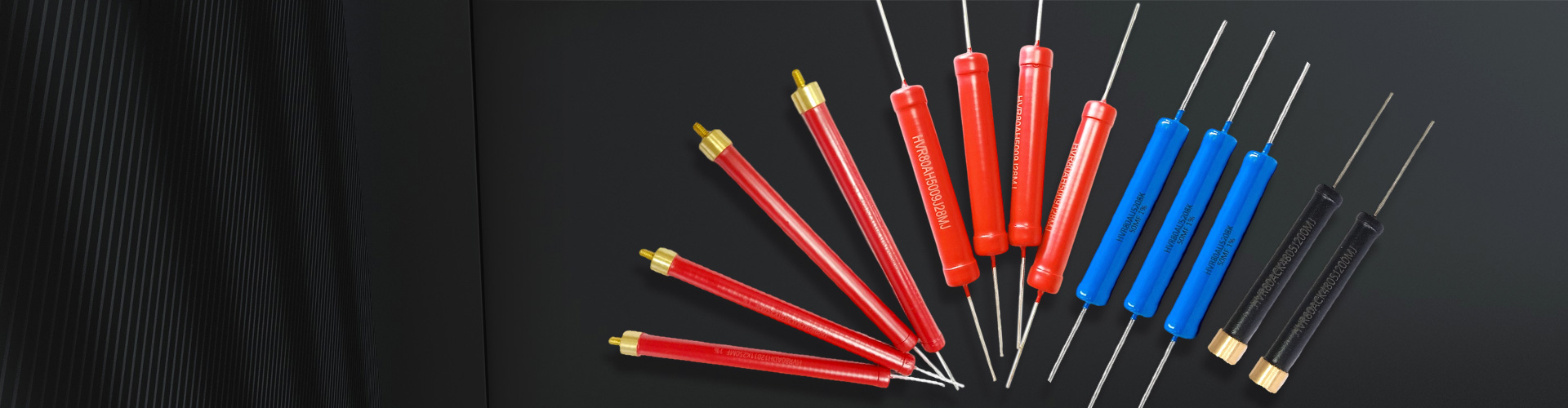


제품 특징
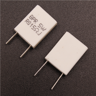
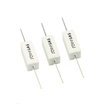
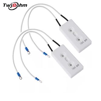
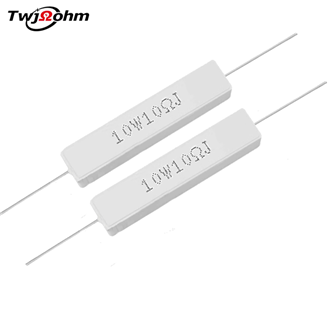
시멘트 저항
Cement resistance
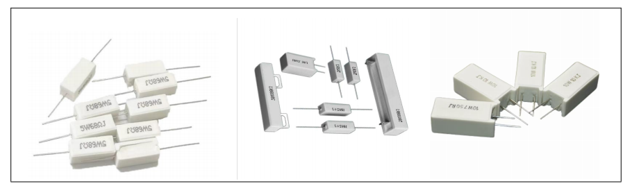
제품 특징 Product Features
1.내진, 내습, 내열 및 좋은 열 방출.Shock resistance, moisture resistance, heat resistance, and good heat dissipation
2.완전히 절연되어 인쇄회로기판에 적용.Completely insulated, suitable for printed circuit boards
3. 도자기 막대에 실을 감고 접선 용접을 하여 정확한 저항치를 만들고 수명을 연장한다.Wrap the wire around the porcelain rod and then weld the joint to produce precise resistance values and extend its lifespan
4.높은 저항값은 금속산화막체로 실을 감는 방식을 대체하여 만든다.High resistance value is made by using metal oxide film instead of winding method
5. 내열성이 우수하고 저항온도계수가 작으며 직선적인 변화를 보인다.Excellent heat resistance, small temperature coefficient of resistance, and linear variation
6.짧은 시간 초과 부하, 낮은 잡음, 임피던스는 오랜 세월 동안 변화가 없습니다.Resistant to short-term overload, low noise, and resistance unchanged for years
7.폭발 방지 성능이 좋아 보호 작용을 한다.Good explosion-proof performance, providing protection
적용 범위 Application Scope
전원 어댑터, 음향 설비, 음향 분주기, 계기 계기, 텔레비전, 자동차 등 설비에 광범위하게 응용된다.
Widely used in power adapters, audio equipment, audio dividers, instruments, televisions, cars, and other devices.
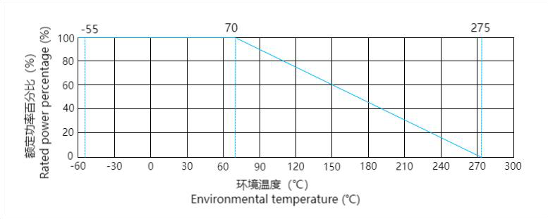
정격 전력 또는 전압/온도 변화 관련 커브
Rated power or voltage/temperature variation related curve
성능 매개 변수 Perforance Parameter
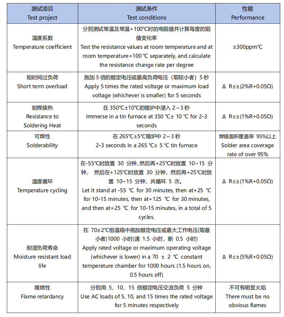
내압성 Pressure Resistant Performance
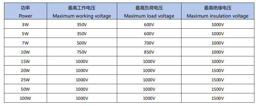
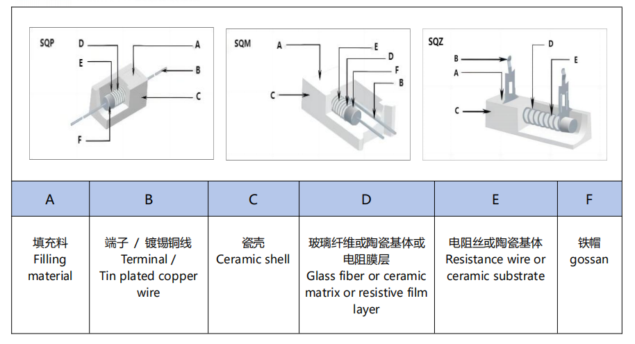
제품 구조 Product Structure:
사양 매개변수 Specification Parameters
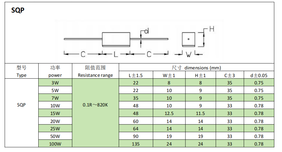
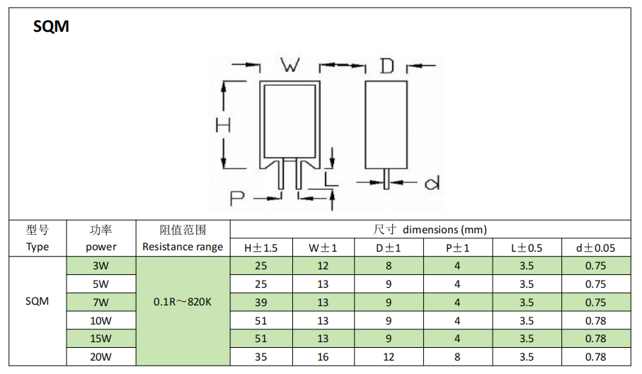
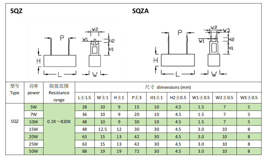
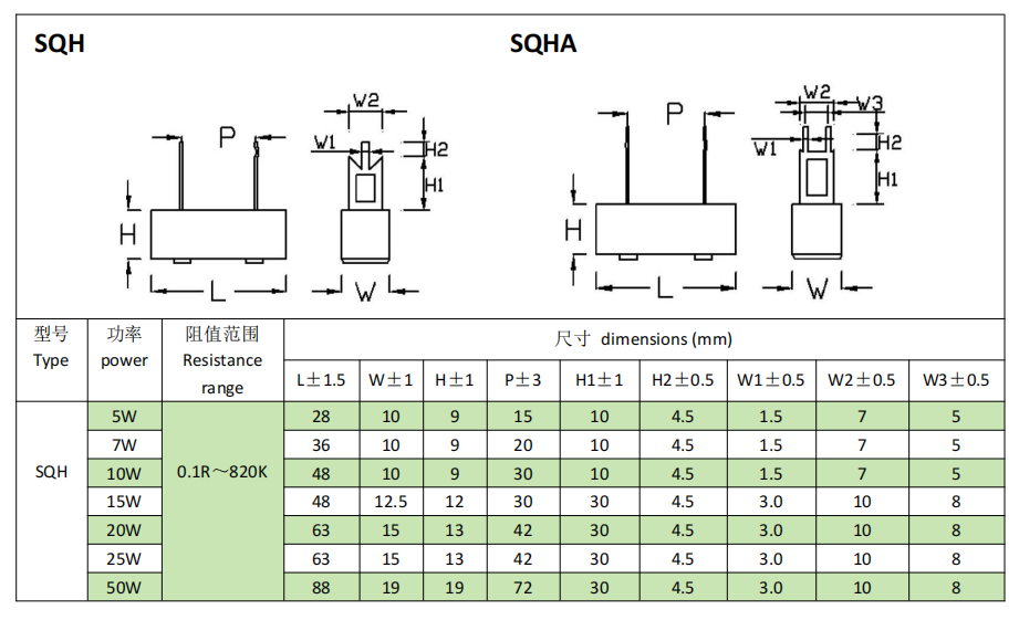
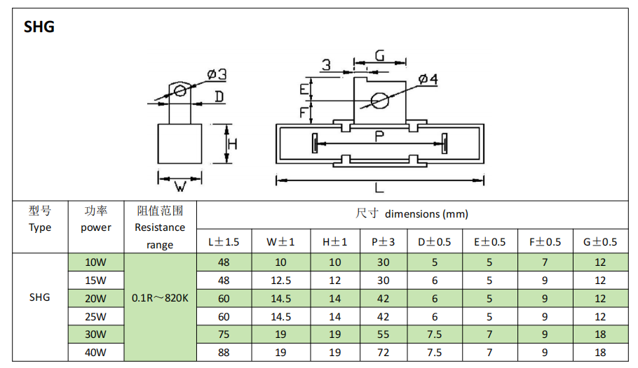
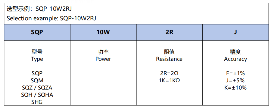
주문 정보 Ordering Information
저항 사용 권장 Suggestions for Using Reslstors
1.저항은 회로를 사용할 때 1.5배의 전력 여유를 남겨두는 것이 좋다. 예를 들어 회로에서 전압 100V, 전류 0.01A, 출력 P=100*0.01=1W를 계산한다. 이때 저항은 1W를 사용할 수 없다. 1*1.5=1.5W를 계산한다. 1.5W의 저항이 없기 때문에 2W의 저항을 사용해야 한다.
It is best to leave 1.5 times the power margin for resistors in circuits. For example, if the voltage in the circuit is 100V and the current is 0.01A, the calculated power is P=100 * 0.01=1W. At this time, a resistor of 1W cannot be used, and 1 *1.5=1.5W is calculated. There is no 1.5W resistor, so a 2W resistor is needed.
2. 저항은 사용 과정에서 저항의 최고 사용 전압을 초과할 수 없다. 예를 들어 저항 1/4W 10K의 최고 사용 전압은 =50V,4.0의 250V가 아닙니다. 또는 1/4W 1M, 계산
 이 시점에서 최대 사용 전압은 계산된 500V가 아닌 4.0의 250V로 둘 중 작은 값을 취합니다.
Resistors should not exceed their maximum operating voltage during use. For example, the maximum operating voltage for resistor 1/4W 10K is V= =50V, not 250V as specified in 4.0. Or 1/4W 1M, calculate
 = 500V the highest operating voltage at this time is 250V in 4.0, instead of the calculated 500V,take the smaller of the two.
실험 프로젝트 Pilot Projects
1. 용접성 테스트 Soldering test
측정된 저항의 도선의 한쪽 끝을 약 45 ℃ 로 기울이는 방식으로 265 ℃ 5 ℃ 의 주석로에 3초 동안 담근 후 꺼내 그 부착성을 검사한다 (상황에 따라 용접제를 사용한다).용접 주석 면적 커버율 95% 이상.
Tilt one end of the wire of the tested resistor at approximately 45 ℃ and immerse it in a 265 ℃ 5 ℃ tin furnace for 3 seconds, then remove it and inspect its adhesion (using soldering flux as appropriate). The coverage rate of soldering area is over 95%.
2. 동선 랠리 테스트 Copper wire tensile test
저항을 인장력 측정 기기에 넣고 저항 양쪽 지시선을 고정하고 손잡이를 흔들어 압력계를 20N으로 돌리고 30초 동안 유지하며 지시선은 당겨져 합격이 될 수 없다.
Place the resistor into the tensile testing instrument, fix the leads at both ends of the resistor, shake the handle to turn the pressure gauge to 20N, and maintain it for 30 seconds,The lead wire cannot be pulled off to be qualified.
3. 절연 내전압 시험 Insulation withstand voltage test
측정된 저항의 도선 한쪽 끝을 계기 클립에 고정한 다음 본체를 은박지로 철모 가장자리에 둘러싸면 이때 측정기기의 다른 시험봉을 본체에 기대어 전압을 최고 절연 전압으로 조정하고 60초 동안 지속되며 뚫지 않으면 합격이다.
Fix one end of the wire of the tested resistor onto the instrument clamp, and then wrap the body with tin foil around the top edge of the iron cap. At this point, place the other test rod of the testing instrument against the body, adjust the voltage to the highest insulation voltage, and continue for 60 seconds. If there is no breakdown, it is considered qualified.
짧은 과부하 테스트 및 계산 방법 Short term overload testing and calculation methods
먼저 테스트한 저항기를 저항치와 와트 수에 따라 2.5배의 정격 전압을 계산한다(2.5배의 전압이 와트 수 저항의 최고 부하 전압을 초과할 경우 와트 수 저항의 최고 부하를 정격 전압으로 계산한다.예: 탄소막의 1/4W의 최고 부하 전압은 500V, 240K저항으로 2.5배의 정격 전압을 계산한다. 612.3V이며, 이때 최고 부하 전압은 612.3V가 아닌 500V로 계산됩니다.)다시 무파교류전기 또는 직류전기로 기한내에 계산한 최고부하전압으로 5초간 전압을 가하면 그 결과는 반드시 무부하상황에서 약 30분간 방치되여야 하며 저항은 이상이 생겨서는 안된다.그 저항의 테스트 전 및 테스트 후의 변화율은 특성 파라미터가 정한 각종 저항 표준을 초과해서는 안 된다.변화율 = (R2-R1)/R1*100%
R1: 시험 후 임피던스를 나타내는 R2
First, calculate 2.5 times the rated voltage of the tested resistor based on its resistance value and wattage (if the calculated 2.5 times voltage exceeds the maximum load voltage of the wattage resistor, the maximum load voltage of the wattage resistor is used as the rated voltage. For example, the maximum load voltage of a carbon film 1/4W is 500V,and the rated voltageis 612.3V calculated based on a 240K Ω resistor. At this time, the maximum load voltage is still calculated as 500V, not 612.3V). The maximum load voltage calculated on a regular basis using non wave alternating current or direct current, with a voltage applied for 5 seconds, must be left unloaded for about 30 minutes without any abnormal resistance. The rate of change of its resistance before and after testing shall not exceed the various resistance standards determined by the characteristic parameters.
Change rate=(R2-R1)/R1 * 100%
R1: represents the resistance before the experiment, R2 represents the resistance after the experiment
5. 긴 수명 시험 Long life test
먼저 테스트 저항을 측정 클립에 고정하고 상호 온도에 영향을 주지 않거나 환기가 과도하게 이루어지도록 서로 배열합니다.상술한 조건이 완성된후 이 측정된 저항측정저항의 정격전압을 첨가하고 그 전압을 가하는 과정은 90분 동안 전압을 가하고 다시 30분을 중지하는것을 일순환으로 하여 1000시간 동안 지속하고 완성된후 다시 항온상태에 놓고 그 저항값을 측정한다.계산 변화율은 특성 파라미터가 정한 각종 저항 표준을 초과해서는 안 된다.
First, fix the test resistors in the measuring clip and arrange them in a way that does not affect the temperature or excessive ventilation between them. After completing the above conditions, add the rated voltage of the measured resistor. The process of applying voltage is to apply voltage for 90 minutes, then stop for 30 minutes as a cycle, and continue for 1000 hours. After completion, place it in a constant temperature state to measure its resistance value. The calculated rate of change shall not exceed the various resistance standards determined by the characteristic parameters.
6. 온도계수 테스트 Temperature coefficient test
먼저 테스트 저항을 실온에서 t1=25 ℃ 의 저항값 R1, 온도 t2=125 ℃ 의 수지 슬롯에 설치한 후 약 5분 동안 측정하고, 동시에 그 저항값 R2를 측정하며, 다음 공식에서 이 저항의 온도계수 (T.C.R) 가 필요한 범위 내에 있는지 구한다.
First, measure the resistance value R1 of the test resistor at t1=25 ℃ at room temperature. Place it in a resin tank at t2=125 ℃ for about 5 minutes, and simultaneously measure its resistance value R2. Use the following formula to determine whether the temperature coefficient (T.C.R) of the resistor is within its required range.

7. 온도 순환 실험 Temperature cycling experiment
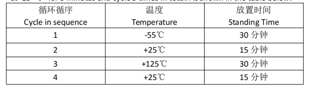
-55 ℃ 에서 30 분, 25 ℃ 에서 15 분, 125 ℃ 에서 30 분.그런 다음 25 ℃ 에서 5 분 동안 배치하여 총 5 회 순환합니다.다음 표와 같습니다.
Leave at -55 ℃ for 30 minutes, then at 25 ℃ for 15 minutes, and finally at 125 ℃ for 30 minutes. Then let it stand at 25 ℃ for 5 minutes and cycle 5 times in total. As shown in the table below:
8. 내온부하 실험 Temperature resistance load test
저항은 70 ± 2 ℃ 항온상자에 정격 전압 또는 최대 작동 전압 (최소자를 취하는 사람) 1000 시간을 가하여 1.5 시간 동안 단전 0.5 를 압박하는 순환입니다.완료되면 항온 상태로 설정하여 임피던스를 측정합니다.계산 변화율은 특성 파라미터가 정한 각종 저항 표준을 초과해서는 안 된다.
Apply the rated voltage or maximum operating voltage (whichever is the minimum) to the resistor in a constant temperature box at 70 ± 2 ℃ for 1000 hours, and cut off power for 0.5 hours after applying pressure for 1.5 hours as one cycle. After completion, measure its resistance by placing it in a constant temperature state. The calculated rate of change shall not exceed the various resistance standards determined by the characteristic parameters.

주소: 4 층, Angu 산업 공원, Tiechang 기술 공원, Shiwan 도시, Boluo 카운티, Huizhou 시, 광동성
이메일 :twj@twjohm.com